
Why Failsafe Actuators Are Essential for Emergency Shutdown (ESD) Systems
- 1 day ago
- 6 min read
An Emergency Shutdown (ESD) system initiates predefined actions to achieve or maintain a defined safe state when hazardous process conditions, equipment failures, gas detection, or loss of utilities create unacceptable risk. Yet control logic cannot isolate a pipeline by itself. The actuator must physically move the valve.
A fail-safe actuator must provide the required output torque and, where operation during loss of normal power is required, a suitable stored-energy or backup-power source must be available to move the ESD valve to its defined safe position.
What Happens When an ESD System Is Triggered?
An ESD system follows a predetermined sequence to isolate dangerous media, stop feed flow, maintain cooling, open a protective route, or place equipment in a controlled state.
The Shutdown Chain: Detection, Command, Actuation, and Isolation
A typical shutdown chain has four stages:
1. A process sensor or manual trip device initiates the shutdown demand.
2. The safety logic solver issues the trip command.
3. The final element—the actuator, valve, and associated accessories—responds to the command.
4. The valve reaches the defined safe position within the required stroke time.
If normal power is lost during the demand, the specified fail-safe energy source must remain capable of completing the required movement.
A correct trip signal cannot compensate for insufficient torque, poor sizing, or incomplete travel. The outcome depends on the complete actuator-valve assembly.
Why Power Loss Must Be Treated as Part of the Emergency
Power failure may accompany the process upset. A standard electric actuator needs incoming power to rotate the valve and may remain in its last position when supply disappears.
A fail safe electric actuator solves this problem by retaining energy for emergency travel. It can therefore complete a defined opening or closing movement without depending on the external power source.
Why a Failsafe Actuator Is the Final Safety Link
The actuator connects the ESD decision with mechanical valve movement. Its response determines whether the process is isolated or redirected.
A Shutdown Signal Cannot Move an ESD Valve by Itself
An ESD command is only an instruction. The electric actuator must convert the available electrical or stored energy into output torque, overcome the valve’s required operating torque, and complete the specified travel.
Required torque changes with pressure differential, seat design, temperature, contamination, and idle time. Sizing should use actual valve torque, not pipe size alone.
Fail-Close, Fail-Open, and the Defined Safe Position
Failsafe does not always mean fail-close. The required state depends on the process hazard.
Safe action | Typical purpose | Example |
Fail-close | Stop hazardous flow | Isolate fuel, chemical feed, or transfer lines |
Fail-open | Preserve protective flow | Maintain cooling, venting, or drainage |
Application-defined | Coordinate several actions | Close one line while opening a safety route |
Risk assessment should define the safe state. The actuator must then be configured and tested to reach it under realistic conditions.
How a Fail Safe Electric Actuator Works
A fail-safe electric design performs normal valve automation while power is available and uses stored energy for emergency travel after power loss.
Normal Operation While Electrical Power Is Available
During normal service, the actuator opens or closes a quarter-turn valve according to the control command. The motor drives the gear train and output shaft to rotate the valve. End-of-travel is controlled by position limits and/or torque-limiting functions, depending on the actuator and valve design.
In a supercapacitor design, the energy-storage unit also charges during powered operation. The actuator can perform ordinary on-off control while keeping reserve energy available for an emergency stroke.
Automatic Valve Positioning When Power Is Lost
When external power is interrupted, stored supercapacitor energy powers the motor and drives the valve toward the preset fully open or fully closed position.
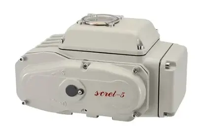
The AOITEC supercapacitor failsafe actuator uses a built-in energy-storage system for automatic emergency positioning without external power. Compared with traditional battery-based solutions, the design provides faster charging, longer service life, and lower maintenance requirements.

It is suitable for ESD systems, oil and gas pipelines, chemical processing, water treatment, and power applications where controlled valve response is required during an outage.
Failsafe Actuator Technologies Compared
Selection should consider energy storage, space, cycling frequency, maintenance, and valve torque.
Standard Electric Actuator vs. Fail Safe Electric Actuator
Comparison point | Standard electric actuator | Fail-safe electric actuator |
Normal operation | Operates with supplied power | Operates with supplied power |
Power-loss behavior | Usually remains in place | Moves to a defined safe position |
Emergency energy | Normally unavailable | Built into the design |
Typical use | Routine automation | Shutdown-critical service |
A standard actuator may suit applications where power loss creates no unsafe position. An ESD valve requires a predictable response, so selection must follow the shutdown philosophy.
Spring-Return vs. Supercapacitor Failsafe Actuator
A spring-return actuator stores mechanical energy in a compressed spring. A supercapacitor fail-safe actuator stores electrical energy and uses the motor to perform the emergency stroke.
Spring mechanisms provide direct return action but can increase actuator size and weight. Compared with battery-based designs, a supercapacitor fail-safe actuator can reduce routine replacement and maintenance requirements.
At AOITEC, our development also emphasizes compact integration and brushless DC technology. Our broader actuator platform includes bracket-free structures and BLDC designs intended to reduce wear, heat generation, and maintenance.

How to Select a Fail Safe Valve Actuator for ESD Service
Selection should begin with process safety, followed by valve mechanics, electrical conditions, and control integration.
Match the Safe Position to the Process Risk
Before selecting an actuator, define:
1. Which flow must stop during an emergency.
2. Which flow must continue for protection.
3. Whether the valve must fail open or fail closed.
4. How long it must remain in that state.
5. What conditions permit a reset.
This avoids selecting equipment before defining what safe operation means for the process.
Verify Torque, Valve Type, Stroke Time, and Power Supply
The actuator must provide enough torque under the worst credible conditions. Review valve breakaway, running, and seating torque, pressure differential, media, temperature, and an appropriate design margin.
Stroke time must also suit the process. Slow closure may allow excessive release, while overly rapid closure can create pressure surge or water hammer. Confirm power compatibility, mounting interface, installation space, and environmental requirements before final selection.
Plan for Control Integration, Testing, and Maintenance
Position feedback should confirm that the complete final element reaches the required safe position within the specified stroke time. Commissioning and periodic proof testing should verify both the ESD trip path and the loss-of-power response.
A practical test program should include:
1. Normal open-close operation.
2. Initiation of the ESD trip input while normal power is available.
3. Simulation of normal power failure.
4. Verification of full valve travel and the specified stroke time.
5. Verification of stored-energy readiness before the emergency stroke.
6. Confirmation of the required safe position and position feedback.
7. Verification of reset, inhibit, and restart permissive behavior.
8. Documentation of pass/fail criteria and test results.
9. Periodic proof testing at intervals defined by the safety requirements and functional-safety assessment.
Partial-stroke testing may be used to identify certain dangerous failures between full-stroke proof tests, but it should not be presented as an automatic replacement for full-stroke testing.
Consider a chemical transfer skid with a normally open feed valve that must close during an outage. A conventional actuator could stop with the valve partly open. A correctly sized fail-close actuator with stored energy can finish the closing stroke and isolate the line. The case shows why ESD performance must be verified by completed valve movement, not signal transmission alone.
Frequently Asked Questions
Q: What is a failsafe actuator in an Emergency Shut Down (ESD) system?
A: A failsafe actuator moves an ESD valve to a predefined safe position when normal power is lost or a shutdown command is issued. It converts the safety decision into mechanical valve movement.
Q: How does a supercapacitor failsafe actuator work during a power failure?
A: The supercapacitor charges during normal powered operation. When external power disappears, stored energy drives the motor so the valve can move to its preset fail-open or fail-close position.
Q: Should an ESD valve fail open or fail closed?
A: It depends on the process risk. A valve usually fails closed when hazardous flow must be isolated. It may fail open when cooling, venting, drainage, or another protective flow must continue.
Q: What is the difference between a spring-return actuator and a supercapacitor failsafe actuator?
A: A spring-return actuator stores mechanical energy in a spring. A supercapacitor failsafe actuator stores electrical energy and uses the motor for emergency travel. They differ in size, torque behavior, maintenance, and installation requirements.
Q: Can a fail safe valve actuator operate both ball valves and butterfly valves?
A: Yes, if the actuator has the correct quarter-turn mounting arrangement and sufficient torque. Actual operating torque, pressure conditions, and safety margin must be checked before selection.


Comments